 En
En English
 عربى
عربى русский
 中文简体
中文简体Content
- 1 What Is Drawing Wire?
- 2 How the Wire Drawing Process Works Step by Step
- 3 What Is a Wire Drawing Machine?
- 4 Main Types of Wire Drawing Machines
- 5 Key Components of a Wire Drawing Machine
- 6 Wire Drawing Die Design and Area Reduction
- 7 Wire Drawing Machine Speed and Production Output
- 8 Common Wire Drawing Defects and How to Prevent Them
- 9 Materials Commonly Processed by Wire Drawing Machines
- 10 Selecting a Wire Drawing Machine: Key Factors to Evaluate
- 11 Wire Drawing vs. Other Metal Forming Processes
What Is Drawing Wire?
Drawing wire is the process of reducing a metal rod or wire to a smaller diameter by pulling it through a series of tapered dies under tension. The result is a wire with tighter dimensional tolerances, improved surface finish, and enhanced mechanical properties compared to the original rod. This cold-working process is fundamental to manufacturing copper electrical wire, steel cable, aluminum conductors, stainless steel springs, and countless other products used across construction, automotive, electronics, and telecommunications industries.
In practical terms, a steel rod of 6.5 mm diameter can be drawn down to 0.10 mm through successive passes, achieving a total area reduction exceeding 99%. The process works because metal is ductile — it deforms plastically without fracturing when pulled through a die at a controlled angle and speed.
How the Wire Drawing Process Works Step by Step
The wire drawing process follows a well-defined sequence that transforms raw rod stock into finished wire with precise specifications:
- Rod preparation: The incoming rod (typically 5.5–13 mm) is cleaned by acid pickling or mechanical descaling to remove mill scale and oxides that would damage dies.
- Pointing: One end of the rod is tapered (pointed) so it can be threaded through the first die and gripped by the drawing block.
- Lubrication: The wire passes through a lubricant box (dry soap powder, oil emulsion, or wet lubricant) to reduce friction and die wear.
- Die drawing: The wire is pulled through a hardened die — typically tungsten carbide for heavy sizes and polycrystalline diamond (PCD) for fine wire — reducing cross-sectional area by 10–30% per pass.
- Intermediate annealing (if needed): After significant cold work, the wire is softened in a furnace (600–900°C for steel) to restore ductility before further drawing.
- Spooling: Finished wire is wound onto coils or reels at controlled tension for shipment or downstream processing.
Each die pass work-hardens the metal, increasing tensile strength. High-carbon steel wire drawn to 2 mm, for example, can reach tensile strengths of 1,800–2,200 MPa — far higher than the 600–900 MPa of the original hot-rolled rod.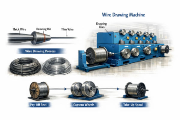
What Is a Wire Drawing Machine?
A wire drawing machine is industrial equipment that mechanizes and automates the drawing process, pulling wire through one or multiple dies at controlled speeds using motorized capstans or drawing blocks. Modern machines range from single-die bull blocks used for heavy rod breakdown to 25-die continuous fine wire drawing machines capable of producing wire thinner than a human hair at speeds exceeding 3,000 m/min.
Wire drawing machines are categorized by material (steel, copper, aluminum), wire diameter range, number of drawing passes (dies), and drive configuration. Selecting the right machine type directly determines productivity, wire quality, and energy consumption.
Main Types of Wire Drawing Machines
Different applications call for different machine configurations. The table below summarizes the most common types:
| Machine Type | Number of Dies | Typical Diameter Range | Common Application |
|---|---|---|---|
| Single-die Bull Block | 1 | 6–20 mm | Heavy rod breakdown, steel bars |
| Multi-die Continuous Machine | 4–25 | 0.5–6 mm | Nails, wire mesh, general steel wire |
| Copper Fine Wire Machine | 10–30 | 0.05–1.5 mm | Electrical conductors, magnet wire |
| Ultra-fine Wire Machine | 20–40 | 0.01–0.08 mm | Medical devices, bonding wire, sensors |
| Wet Drawing Machine | Up to 30+ | 0.10–2.0 mm | High-carbon steel cord, spring wire |
Dry vs. Wet Drawing Machines
The lubrication method splits machines into two major families. Dry drawing machines use powdered lubricants (soap, lime, borax) and are standard for steel wire down to about 0.5 mm. Wet drawing machines submerge both the dies and capstans in an oil-water emulsion, enabling fine and ultra-fine wire drawing at very high speeds with superior cooling and die life.
Key Components of a Wire Drawing Machine
Understanding the machine's anatomy helps operators troubleshoot problems and optimize performance:
- Drawing die: The core tool — a nib (tungsten carbide or PCD diamond) mounted in a steel casing. Die geometry (approach angle typically 6–15°, bearing length) determines deformation quality and die life.
- Drawing capstan/block: A rotating drum that applies tension to pull the wire through the die. Diameter and surface finish affect wire wrapping and slippage.
- Pay-off stand: Holds and controls the feed reel, maintaining correct back tension to prevent coil collapse or wire kinking on entry.
- Lubrication system: Die boxes for dry machines or a recirculating emulsion tank with filtration for wet machines. Contaminated lubricant causes surface defects and broken wire.
- Take-up/spooler: Winds finished wire onto bobbins or coils at controlled tension. Precision traversing ensures uniform layer winding.
- Drive system: AC variable-frequency drives (VFDs) allow precise capstan speed control and speed synchronization across multiple drawing blocks, critical to avoiding wire breakage.
- Cooling system: Water-cooled capstans or die holders dissipate heat generated by deformation and friction, protecting wire properties and die geometry.
Wire Drawing Die Design and Area Reduction
The die is the most critical consumable in wire drawing. Its geometry controls deformation efficiency, surface quality, and wire mechanical properties.
Die Zones
A standard drawing die has four distinct zones:
- Entry/bell zone: Guides the wire into the die without sharp contact.
- Approach/reduction zone: The angled surface (typically 2α = 12–24° total included angle for steel) where actual diameter reduction occurs.
- Bearing/land zone: A short parallel section that sizes the wire to final diameter and improves roundness. Typical length is 25–35% of exit diameter.
- Exit/back relief zone: Prevents wire scoring on exit and facilitates lubrication film removal.
Area Reduction per Pass
Area reduction (r) is calculated as: r = (A₀ − A₁) / A₀ × 100%, where A₀ is the entry cross-section and A₁ is the exit cross-section. Typical values are:
- Soft copper and aluminum: 20–35% per pass
- Low-carbon steel: 15–25% per pass
- High-carbon or stainless steel: 10–18% per pass
- Ultra-fine wire (precious metals): 5–12% per pass
Excessive reduction per pass raises the risk of center burst defects and wire breaks, especially in high-carbon materials.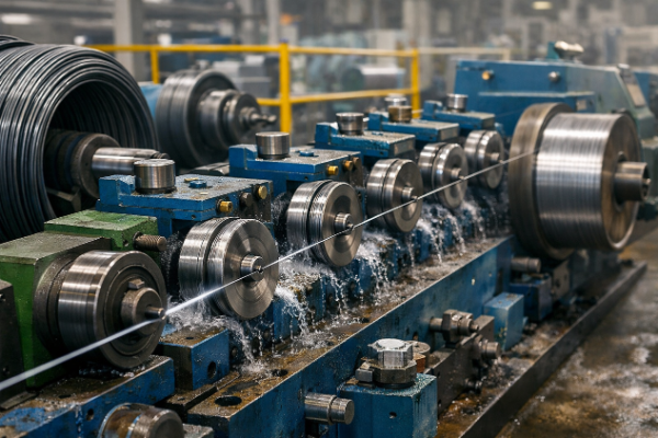
Wire Drawing Machine Speed and Production Output
Machine speed is one of the most important parameters affecting both productivity and wire quality. Drawing speed varies enormously depending on material and wire size:
| Material | Final Diameter | Typical Drawing Speed |
|---|---|---|
| Low-carbon steel | 2–5 mm | 3–15 m/s |
| High-carbon steel cord | 0.15–0.40 mm | 20–40 m/s |
| Copper (medium wire) | 0.5–2.0 mm | 10–25 m/s |
| Copper (fine wire) | 0.05–0.2 mm | 30–50 m/s |
| Aluminum (electrical) | 1–4 mm | 8–20 m/s |
High-speed machines require proportionally advanced lubrication, cooling, and die materials to maintain consistent quality. Increasing speed by just 20% without adequate cooling can raise die temperature by 80–120°C, rapidly accelerating wear.
Common Wire Drawing Defects and How to Prevent Them
Even well-maintained machines can produce defective wire if process parameters drift. Recognizing defect causes speeds up corrective action:
- Wire breakage: Most commonly caused by excessive reduction per pass, worn or incorrectly sized dies, surface seams in incoming rod, or inadequate lubrication. Breakage rate above 1 break per ton signals a systemic problem.
- Diameter variation (ovality): Results from worn die bearing zone, uneven capstan tension, or vibration. Copper magnet wire with ovality above 0.5% causes insulation failures in motors.
- Surface scratches and seams: Caused by die nicks, contaminated lubricant, or debris in the die box. Critical for stainless steel and medical-grade wire.
- Center bursts (Chevron cracks): Internal fractures invisible on the surface, caused by high die angles combined with low reduction. Particularly dangerous in prestressed concrete strand wire.
- Residual stress cracking: Excessive cold work without intermediate annealing creates high internal stresses that cause delayed cracking in coils after drawing.
Materials Commonly Processed by Wire Drawing Machines
Wire drawing machines process a broad spectrum of metals, each with distinct challenges:
- Low-carbon steel (≤0.10% C): Used for nails, mesh, barbed wire, and general engineering. High ductility allows large reductions per pass.
- High-carbon steel (0.60–0.95% C): Used for spring wire, tire bead, PC strand, and ropes. Requires tight control of patenting (heat treatment) before drawing to achieve the required microstructure.
- Stainless steel: Work-hardens very rapidly; requires frequent annealing and specialized lubricants (chlorinated oils or oxalate coating).
- Copper and copper alloys: The highest volume non-ferrous drawn wire globally. Soft copper requires no interpass annealing for moderate reductions but must be annealed to maintain conductivity for electrical grades.
- Aluminum and aluminum alloys: Drawn for overhead power lines (AAC, AAAC, ACSR conductors) and building wire. Low strength requires gentler die angles and careful tension control.
- Tungsten and molybdenum: Drawn for lamp filaments and high-temperature applications; requires elevated temperature drawing and diamond dies.
Selecting a Wire Drawing Machine: Key Factors to Evaluate
Purchasing or specifying a wire drawing machine involves more than matching diameter range. Evaluate these parameters carefully before committing:
- Maximum drawing force (kN): Must exceed the yield strength of the wire cross-section at the first die exit. Undersized machines break wire or stall under load.
- Number of drawing passes: More passes allow finer final diameter and better distribution of work per die, but increase machine footprint and capital cost.
- Drive type and control: VFD-controlled AC drives provide smooth speed ramping and synchronization. Older slip-clutch systems are prone to tension spikes that break fine wire.
- Cooling capacity: Verify that capstan cooling and lubricant chilling can maintain temperatures within limits at maximum production speed.
- Die change time: On a multi-die machine producing 3 mm steel wire at 10 m/s, a 10-minute die change represents roughly 6,000 m of lost production. Quick-change die holders significantly reduce downtime.
- Automation and monitoring: Modern machines incorporate laser diameter gauges, tension sensors, and PLC controls that detect breaks and parameter drift in real time, reducing scrap rates by 15–30% compared to manually monitored machines.
Wire Drawing vs. Other Metal Forming Processes
Wire drawing is sometimes confused with related processes. Understanding the differences clarifies when each method applies:
- Wire drawing vs. extrusion: In extrusion, metal is pushed through a die; in drawing, it is pulled. Drawing produces better dimensional accuracy and work-hardening; extrusion is preferred for non-ductile alloys and hollow profiles.
- Wire drawing vs. rolling: Rolling uses compression between rolls, suitable for flat products and large rods. Drawing is preferred for round wire below about 8 mm where die confinement ensures precise roundness.
- Wire drawing vs. swaging: Swaging uses radial hammer blows to reduce diameter, preferred for tapered products or materials sensitive to tensile stress during die drawing.
For producing long lengths of wire with tight diameter tolerance (±0.005 mm achievable on fine copper), wire drawing through progressive dies remains the most efficient and cost-effective cold-forming method available.


")


