 En
En English
 عربى
عربى русский
 中文简体
中文简体Content
- 1 What a Wire Drawing Machine Does — and Why It Matters
- 2 The Wire Drawing Process: Step by Step
- 3 Main Types of Wire Drawing Machines
- 4 Wire Drawing Machine Specifications Compared by Application
- 5 Dies: The Component That Defines Wire Quality
- 6 Lubrication: Critical to Machine Performance and Wire Quality
- 7 Key Factors When Selecting a Wire Drawing Machine
- 8 Common Wire Drawing Problems and Their Root Causes
What a Wire Drawing Machine Does — and Why It Matters
A wire drawing machine reduces the diameter of metal rod or wire by pulling it through a series of progressively smaller dies under tension. The output is wire with a precise diameter, improved mechanical properties, and a smoother surface finish — qualities that cannot be reliably achieved through rolling or extrusion alone.
Wire drawing is the foundational process behind virtually every wire product in modern manufacturing — from electrical conductors and automotive cables to spring steel, surgical sutures, and piano wire. A machine that starts with 5.5 mm steel rod can reduce it to 0.1 mm or finer through successive drawing passes, each removing a controlled percentage of cross-sectional area.
Selecting the right wire drawing machine — whether for copper, aluminum, steel, or specialty alloys — depends on understanding the process mechanics, machine configurations, die design, lubrication requirements, and the final wire specifications your application demands. This guide covers each of those areas with the specificity needed to make an informed equipment decision.
The Wire Drawing Process: Step by Step
The drawing process follows a consistent mechanical logic regardless of the material being drawn. Understanding each stage helps diagnose problems and optimize output quality.
- Pointing: The leading end of the rod is tapered — either by swaging, rolling, or grinding — so it can be threaded through the die opening and gripped by the drawing capstan or block.
- Die entry: The pointed wire enters the die's bell (entry cone), which guides it into the approach angle where deformation begins.
- Reduction zone: The wire is compressed radially as it passes through the die's bearing zone. Cross-sectional area decreases while length increases proportionally. Reductions per pass typically range from 15% to 25% for steel and up to 30% to 35% for softer metals like copper and aluminum.
- Bearing zone: A short cylindrical section that controls final diameter and surface finish.
- Back relief: A slight taper at the die exit that prevents the wire from binding as it leaves.
- Winding: The drawn wire coils onto a capstan or spool for the next pass or final packaging.
Each pass through a die work-hardens the wire due to plastic deformation. For materials like high-carbon steel and stainless, intermediate annealing (softening through heat treatment) may be required after several passes to restore ductility before drawing can continue. Copper and aluminum typically allow more reductions before annealing is needed.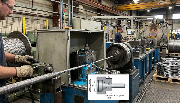
Main Types of Wire Drawing Machines
Wire drawing machines are categorized primarily by the number of drawing blocks (single vs. multi-pass), the arrangement of those blocks, and the type of material and wire gauge being processed. Each configuration suits a different production scenario.
Single-Block (Single-Die) Drawing Machines
The simplest configuration: one die, one capstan. The rod passes through a single die and winds onto a rotating drum. Single-block machines are used for heavy wire and rod drawing — typically reducing rod from 5–12 mm down to 2–4 mm in a single pull. They are common as the first stage in a multi-machine drawing line and are also used for specialty applications where frequent die changes are needed.
Drawing speeds for single-block machines working heavy rod are typically 1 to 5 meters per second. The advantage is mechanical simplicity and ease of setup; the limitation is that only one reduction is achieved per machine pass.
Multi-Pass (Continuous) Drawing Machines
Multi-pass machines thread wire through a series of dies and capstans in a single continuous pass. Each capstan rotates faster than the previous one to compensate for the wire's increased speed and length after each reduction. These machines are the workhorses of wire drawing — a single 12-die machine can take 5.5 mm rod and draw it down to under 1 mm without stopping.
Modern multi-pass machines for fine copper wire can achieve exit speeds exceeding 30 meters per second, with some high-speed fine wire machines reaching 40–50 m/s. The number of dies in the machine typically ranges from 6 to 25 depending on the final gauge and material.
Wet Drawing Machines
In wet drawing machines, the dies and capstans are fully submerged in a liquid lubricant-coolant solution. This is the standard configuration for fine and ultra-fine wire drawing — diameters below approximately 0.5 mm — where the heat generated at high drawing speeds would otherwise damage the wire or the dies. Wet machines are dominant in the production of magnet wire, telecommunications wire, and fine stainless steel wire.
Dry Drawing Machines
Dry drawing machines use powdered or paste lubricants rather than liquid baths. They are used for medium to coarse wire, particularly steel wire in the 0.5–5 mm range, where dry lubricants such as sodium or calcium stearate provide adequate lubrication without the complications of a liquid system. Steel tire cord and spring wire are commonly produced on dry drawing equipment.
Straight-Line Drawing Machines
In a straight-line machine, the wire travels horizontally through the dies without wrapping around intermediate capstans. This eliminates the bending stress introduced by winding around a drum, making straight-line machines preferred for hard, brittle, or high-value materials — such as tungsten, molybdenum, titanium wire, and welding electrode wire — where bending fatigue during drawing would cause breaks.
Wire Drawing Machine Specifications Compared by Application
| Machine Type | Typical Input Diameter | Typical Output Diameter | Drawing Speed | Common Materials |
|---|---|---|---|---|
| Single-block (rod breakdown) | 8–12 mm | 2–6 mm | 1–5 m/s | Steel, copper rod |
| Multi-pass dry | 2–6 mm | 0.5–3 mm | 5–15 m/s | Carbon steel, spring wire |
| Multi-pass wet (medium) | 1–3 mm | 0.1–1 mm | 15–30 m/s | Copper, aluminum, stainless |
| Fine/ultra-fine wet | 0.3–1 mm | 0.01–0.1 mm | 30–50 m/s | Copper, gold, platinum |
| Straight-line | 1–5 mm | 0.3–3 mm | 1–10 m/s | Tungsten, titanium, welding wire |
Dies: The Component That Defines Wire Quality
The drawing die is the heart of the process. Die geometry, material, and surface finish directly determine wire diameter tolerance, surface quality, and die service life. A poorly specified or worn die produces wire that is out of tolerance, rough, or prone to breakage.
Die Materials
- Tungsten carbide: The standard die material for most steel and medium-wire applications. Excellent wear resistance, cost-effective, available in a wide range of grades. Typical service life drawing carbon steel wire: 200–500 kg of wire per die depending on wire hardness and reduction.
- Polycrystalline diamond (PCD): Used for fine and ultra-fine wire drawing of copper and precious metals. Dramatically longer service life than carbide — often 10–50× longer — justifying the significantly higher cost for high-volume fine wire production.
- Natural diamond: Still used for the finest wire gauges below approximately 0.05 mm, where the crystallographic perfection of natural diamond provides surface finishes and dimensional tolerances that synthetic alternatives cannot match.
- Ceramic: Used in specific applications such as drawing stainless steel or titanium where chemical reactivity between the wire and carbide would cause accelerated wear.
Die Angle and Reduction Schedule
The die approach half-angle — the angle between the die axis and the tapered reduction zone — typically ranges from 6° to 12° for most applications. A smaller angle reduces drawing force and die wear but increases the contact length and friction. A larger angle shortens contact but increases redundant deformation, which raises wire temperature and work-hardening rate. The optimal angle for a given material and reduction is determined empirically and is a closely held parameter in commercial wire drawing operations.
The reduction schedule — how much area reduction is assigned to each die in a multi-pass machine — must be balanced so that no single die is overloaded while the machine operates at peak throughput. Typical area reductions per pass are 17–22% for steel and 20–30% for copper. Pushing above these thresholds increases wire break frequency and die wear exponentially.
Lubrication: Critical to Machine Performance and Wire Quality
Lubrication in wire drawing serves three functions: reducing friction between the wire and die, removing heat generated by deformation and friction, and preventing welding or galling between the wire surface and die material. Getting lubrication wrong is the single most common cause of premature die failure, excessive wire breaks, and poor surface quality.
- Dry lubricants (soap powders): Sodium stearate and calcium stearate are the most common dry lubricants for steel wire drawing. The wire is pre-coated with a lime or borax carrier layer that reacts with the soap to form a zinc soap film at the die interface. Effective for rod breakdown and medium wire but not suitable for fine wire.
- Wet lubricants (emulsions and neat oils): Water-based emulsions containing synthetic lubricant additives are standard for wet drawing machines. Concentration is typically maintained between 3% and 10% by volume, with pH controlled between 8.5 and 9.5 to prevent bacterial growth and corrosion. Neat oils (non-emulsified) are used for specific stainless and specialty alloy applications.
- Metallic coatings: For very high-carbon steel (tire cord, PC strand wire), the rod is coated with brass or zinc by electroplating or hot-dip patenting before drawing. These metallic coatings act as solid lubricant carriers and are consumed during drawing, depositing a thin lubricating film at the die interface.
Key Factors When Selecting a Wire Drawing Machine
Purchasing or specifying a wire drawing machine requires matching multiple technical parameters to your production requirements. These are the factors that have the most impact on output quality, operating cost, and return on investment:
Material and Wire Gauge Range
Define your input and output diameter range before evaluating any machine. A machine optimized for copper fine wire drawing is not suitable for steel rod breakdown, and vice versa. If your product range spans a wide gauge window — for example, 5 mm down to 0.3 mm — you will likely need two machines in series rather than a single unit.
Motor Power and Drawing Force
Drawing force is proportional to the wire's cross-sectional area, the yield strength of the material, and the total area reduction per pass. Undersizing motor power results in stalled draws and excessive wire breaks; oversizing wastes capital and energy. For medium steel wire machines processing 1–3 mm wire, installed motor power typically ranges from 15 kW to 75 kW per drawing block depending on the number of passes and drawing speed.
Speed Control and Synchronization
In multi-pass machines, the speed of each capstan must be precisely synchronized to maintain correct back-tension between passes. Modern machines use variable frequency drives (VFDs) with closed-loop tension control on each block, allowing automated adjustment to wire elongation variations. Older machines use mechanical speed ratios that require manual tuning when changing wire grades or die schedules.
Inline Annealing Capability
For copper and aluminum wire drawing, continuous inline annealing — passing the finished wire through a short resistive heating zone before the take-up spool — restores ductility without a separate furnace anneal cycle. Inline annealing can eliminate an entire separate processing step, significantly reducing production lead time and energy cost per kilogram of wire produced. Verify whether the machine's exit speed is compatible with the thermal residence time required for adequate annealing of your target alloy.
Break Detection and Automatic Restart
Wire breaks are an unavoidable part of drawing operations, especially on fine wire machines running at high speed. The cost impact of a break depends largely on how quickly the machine stops and how quickly the operator can re-thread and restart. Modern machines include optical or contact-based break detectors that stop the machine within milliseconds of a break and, on some models, can automatically re-thread and restart without operator intervention. On a high-speed fine wire machine running at 40 m/s, reducing re-thread time from 15 minutes to 2 minutes can recover hundreds of hours of production annually on a single machine.
Common Wire Drawing Problems and Their Root Causes
Diagnostic knowledge of common drawing problems reduces downtime and scrap. Most defects trace back to one of three sources: die condition, lubrication failure, or material inconsistency.
- Frequent wire breaks: Most often caused by excessive reduction per pass, worn or cracked dies, inadequate lubrication, or hard spots in the incoming rod due to segregation or improper rolling mill practice. Check die condition first, then review the reduction schedule.
- Surface scoring or die lines: Indicates die wear, die surface contamination, or lubricant breakdown. Replace the die and flush the lubrication system. Scoring left unaddressed will propagate to downstream dies and degrade the entire product length.
- Diameter variation along the wire: Can result from tension fluctuations (check VFD calibration and capstan surface condition), worn bearing zones in dies, or inconsistent incoming rod diameter.
- Excessive heat generation: Points to lubrication insufficiency, excessive drawing speed for the lubricant system's cooling capacity, or reduction per pass exceeding the material's thermal tolerance. Copper wire temperature at the die exit should generally remain below 150°C to prevent surface oxidation.
- Coiling or cast problems on spooled wire: Residual stress from the drawing process can cause wire to spring off the spool or form inconsistent coils. Adjusting back-tension on the final capstan or adding a straightening roller before the take-up spool typically resolves this.


")


