Language
 中文简体
 English
 عربى
 русский
Content
- 1 What Is 20 Gauge Wire in mm? The Short Answer
- 2 Why a Bigger Gauge Number Means a Smaller Wire
- 3 20 Gauge to mm Conversion Table
- 4 Solid Versus Stranded: Why the mm Value Moves
- 5 Current Carrying Capacity of 20 Gauge Wire
- 6 Where 20 Gauge Wire Shows Up in Real Cable Production
- 7 From 8 mm Rod to 0.812 mm: How 20 AWG Is Actually Made
- 8 Practical Checks Before You Convert a Gauge Value
- 9 Frequently Asked Questions
If you work with cables, you have almost certainly had this conversation: a customer sends over a drawing marked "20 AWG" and someone on the floor asks what that actually means in millimetres. The quick answer is that 20 gauge wire, in the American Wire Gauge system used for electrical conductors, has a diameter of 0.812 mm and a cross-sectional area of 0.518 mm².
That answer is correct, but it is also incomplete. The number you should write on a process sheet depends on whether you are measuring a solid conductor, a stranded bundle, a tinned wire, or a finished insulated core. This article walks through the conversion the way we use it ourselves, and points out the places where a straight table lookup can quietly cause problems.
What Is 20 Gauge Wire in mm? The Short Answer
When engineers say "20 gauge" without further qualification, they normally mean AWG 20 for an electrical conductor. The nominal figures for a solid, uncoated copper conductor are stable and well established, and they are the ones worth memorising.
These values describe the conductor itself, at a reference temperature of 20 °C, before any insulation, tinning or stranding is taken into account. That is an important distinction, because the finished wire you pull off a reel is almost always larger than 0.812 mm.
| Property | Metric value | Imperial value |
|---|---|---|
| Conductor diameter | 0.812 mm | 0.0320 in |
| Cross-sectional area | 0.518 mm² | 1020 circular mils |
| Nearest metric equivalent | 0.5 mm² | — |
| DC resistance at 20 °C | 33.3 Ω/km | 10.15 Ω per 1000 ft |
| Typical stranded build | 10 × 0.255 mm | 10 strands of 30 AWG |
Why a Bigger Gauge Number Means a Smaller Wire
The AWG system runs backwards compared with almost every other size convention. The larger the number, the smaller the conductor. A 20 AWG wire is thinner than an 18 AWG wire, and much thinner than a 12 AWG wire. If you are used to metric notation, where a bigger number means more copper, this reversal is the single most common source of confusion.
The scale is geometric rather than linear. Each step up in gauge number reduces the diameter by roughly 11 percent, which in turn reduces the cross-sectional area by about 21 percent. Two simple rules make the whole system manageable in practice:
- Three gauge steps change the area by a factor of about two. Moving from 20 AWG up to 17 AWG roughly doubles the copper area, from 0.518 mm² to 1.038 mm².
- Six gauge steps change the diameter by a factor of about two. Doubling 0.812 mm gives 1.624 mm, which is almost exactly the diameter of 14 AWG.
It is also worth being precise about which gauge you are dealing with. The British Standard Wire Gauge, the older Birmingham gauge, and non-electrical gauge systems used for needles, sheet metal and shotgun bores all use the word "gauge" to mean something entirely different. A 20 gauge value from one of those tables has nothing to do with the 0.812 mm conductor discussed here. Whenever a drawing arrives without a system name, confirm it before you set a die.
20 Gauge to mm Conversion Table
Most conversions on a cable line are not done in isolation. A designer compares 20 AWG against neighbouring sizes to decide whether there is enough copper for the current involved, or whether a larger core will still fit inside a given jacket. The table below covers the range we see most often in control, data and instrumentation cables.
| AWG size | Diameter (mm) | Area (mm²) | DC resistance (Ω/km) |
|---|---|---|---|
| 10 AWG | 2.588 | 5.261 | 3.28 |
| 12 AWG | 2.053 | 3.309 | 5.21 |
| 14 AWG | 1.628 | 2.081 | 8.28 |
| 16 AWG | 1.291 | 1.309 | 13.2 |
| 18 AWG | 1.024 | 0.823 | 20.9 |
| 20 AWG | 0.812 | 0.518 | 33.3 |
| 22 AWG | 0.644 | 0.326 | 52.9 |
| 24 AWG | 0.511 | 0.205 | 84.2 |
| 26 AWG | 0.405 | 0.129 | 134.5 |
Solid Versus Stranded: Why the mm Value Moves
The 0.518 mm² figure describes conductor area, not geometry, and that is where a lot of confusion starts. A solid 20 AWG wire is a single round conductor of 0.812 mm. A stranded 20 AWG conductor contains the same total copper area, but it is built from many finer wires, so the outside diameter is larger than 0.812 mm.
A classic North American build is 10 strands of 30 AWG, each 0.255 mm across. Ten of those strands add up to 0.510 mm², which is close enough to the nominal 0.518 mm² to be sold as 20 AWG. Because the strands sit in layers rather than in a single row, the finished bundle measures roughly 0.95 to 1.0 mm across, depending on the lay length and how tightly the strands are compacted.
It is surprisingly easy to pick the wrong construction. Seven strands of 0.32 mm look like a sensible choice and measure close to 0.81 mm in individual strand size, but they add up to 0.563 mm², which is actually nearer to 19 AWG. On paper the difference looks trivial; on a resistance test or a weight-per-kilometre calculation it becomes real money.
One more layer of confusion: the insulated wire on the shelf is not 0.812 mm. A 20 AWG hook-up wire with a typical PVC wall thickness will measure around 1.5 to 1.7 mm overall. When a customer quotes an outside diameter, always ask whether that figure refers to the conductor, the core, or the finished cable.
Current Carrying Capacity of 20 Gauge Wire
Ampacity is not a property of the gauge alone. It depends on the insulation temperature rating, how many conductors are bundled together, whether the cable is in free air or in a conduit, and the ambient temperature of the installation. For 20 AWG copper, the commonly quoted working range is wide, and the spread is entirely explained by those variables.
- Single insulated conductor in free air: roughly 5 to 11 A, depending on insulation class and permitted temperature rise.
- Conductor inside a multi-core cable or a tight bundle: typically 1.5 to 3 A, because heat cannot escape as easily.
- Signal and instrumentation cores: usually operated well below 1 A, where voltage drop rather than heating sets the limit.
Resistance is often the more practical number. At 33.3 Ω/km, a 100 metre run of 20 AWG copper contributes about 3.3 Ω to the circuit. In a 24 V sensor loop drawing 100 mA, that is a drop of roughly 0.33 V, which may or may not be acceptable depending on the input threshold of the receiving device. Designers who only check ampacity tables and skip the resistance check are the ones who end up adding a repeater later.
For practical purposes, 20 AWG and 0.5 mm² are treated as interchangeable in low-voltage control and signal work. The difference in copper area is a little under four percent, which is smaller than the tolerance on most drawing dies.
Where 20 Gauge Wire Shows Up in Real Cable Production
Because 20 AWG sits in the middle of the fine wire range, it appears in an unusually wide spread of finished products. In our experience with customers across the cable industry, the most common destinations are:
- Control and signal cores inside multi-core control cables and industrial automation cables.
- Instrumentation and data cable cores, where a small conductor keeps capacitance and cable weight down.
- Panel and hook-up wire, including tinned versions used for solderability.
- Sensor, thermocouple and test lead wire, often in stranded form for flexibility.
- Automotive harness signal lines, where vibration resistance favours stranded construction.
- Audio, microphone and low-level signal cables.
- Small winding and coil applications, sometimes with an enamel coating rather than plastic insulation.
What these applications share is a need for consistent diameter and consistent resistance rather than high current capacity. That shifts the manufacturing priority towards dimensional accuracy, surface quality and annealing consistency rather than towards raw pulling speed.
From 8 mm Rod to 0.812 mm: How 20 AWG Is Actually Made
Most people meet 20 AWG as a number in a table. On a production line it is a moving target, and the route from copper rod to finished conductor follows a predictable sequence of reductions.
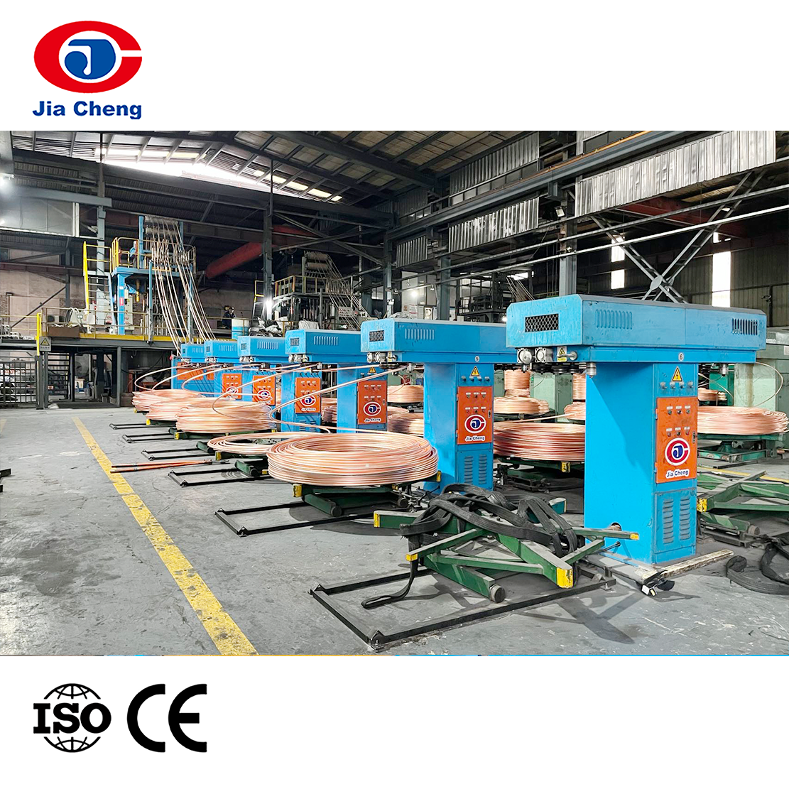
The first stage is rod breakdown. An 8 mm oxygen-free copper rod is pulled down to roughly 2.5 to 3.5 mm on a copper wire processing machine, usually with emulsion lubrication and water cooling to keep the conductor from work hardening too quickly. Getting this first reduction right matters, because defects introduced at the rod stage rarely disappear further down the line.
Intermediate drawing then takes the conductor from around 3 mm down to about 1.2 mm. Machines in this class typically run with slip or non-slip capstan arrangements and are set up so the wire exits with a clean, round cross-section and no surface scoring.
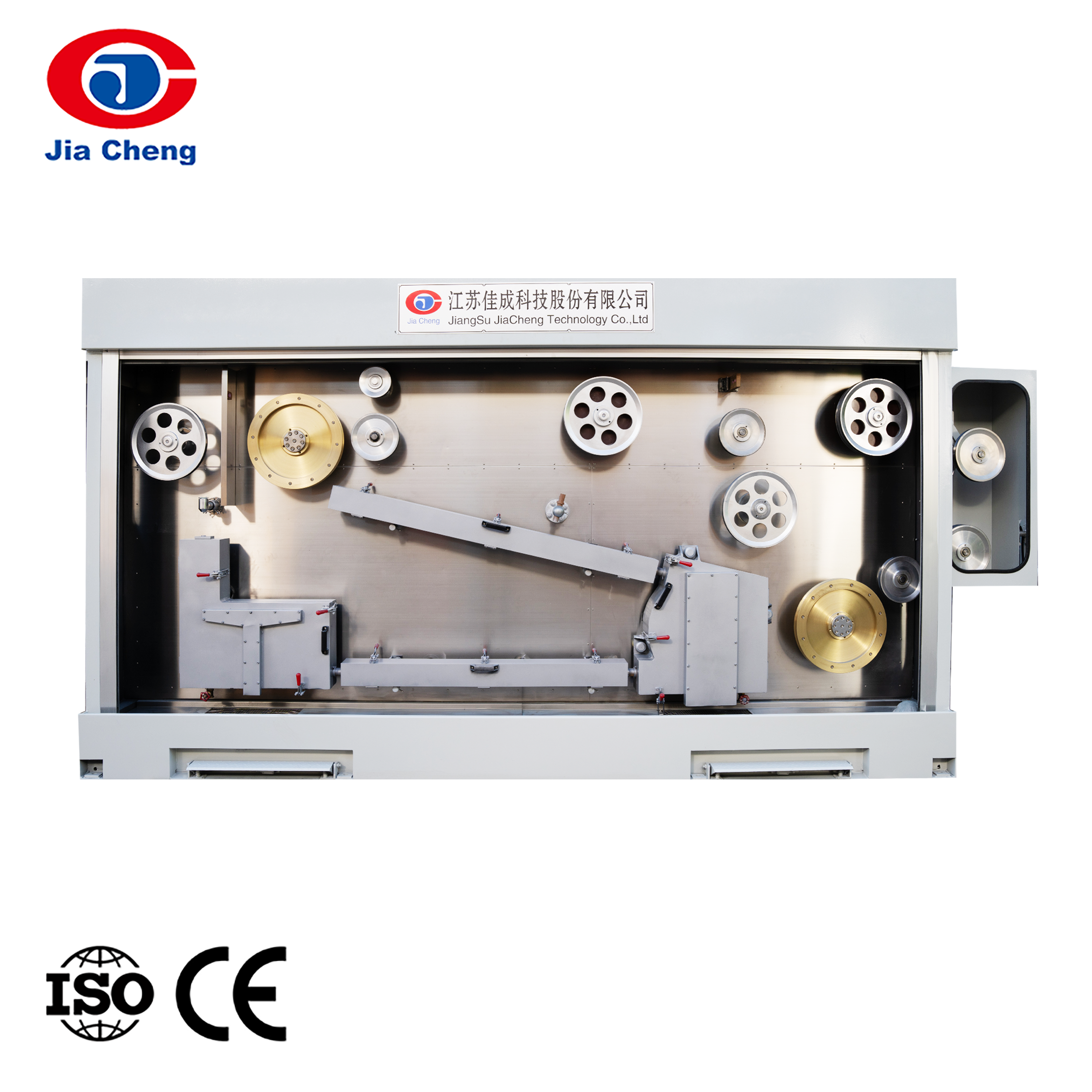
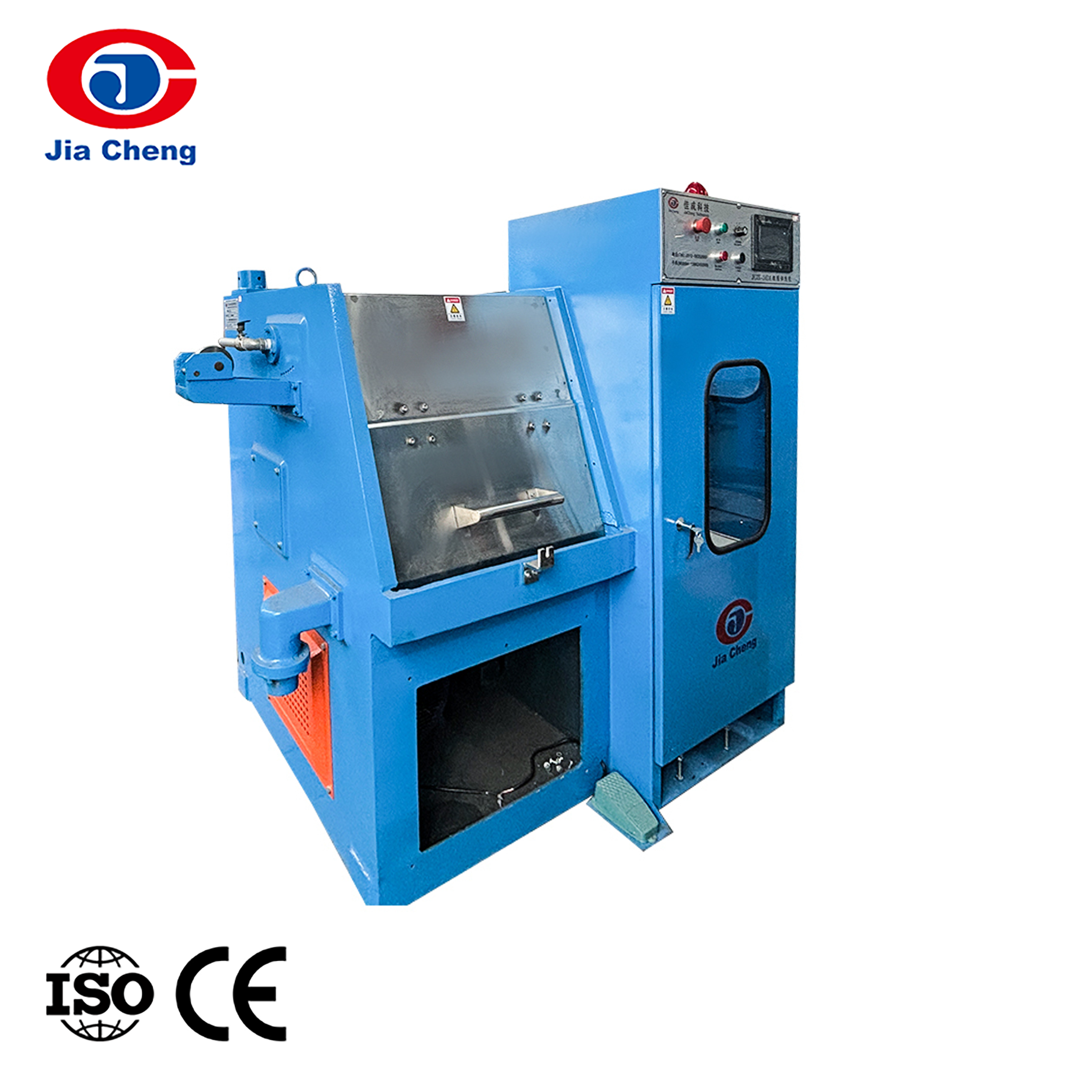
Fine drawing does the last part of the job, and this is where 0.812 mm is produced. A fine wire drawing machine with an integrated annealer carries the conductor through the final dies and then softens it in line, restoring the elongation that the drawing process has consumed. Without that annealing step, the wire will meet the dimensional specification but fail the elongation and bend requirements that most cable standards impose.
 Fine Wire Drawing Machine With Inline Annealer for CopperCombines copper wire drawing and online annealing on one line to restore elongation and support continuous pay-off, drawing, annealing, cooling, and take-up.View Product →
Annealing quality is where a lot of 20 AWG problems originate. Under-annealed wire cracks during subsequent bunching or extrusion; over-annealed wire loses tensile strength and stretches under tension. Modern online annealing units control temperature and current density closely enough to hold elongation within a narrow band across a full reel, which is what downstream processes need.
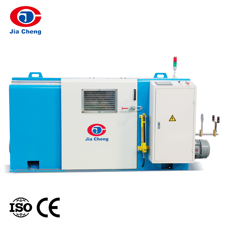
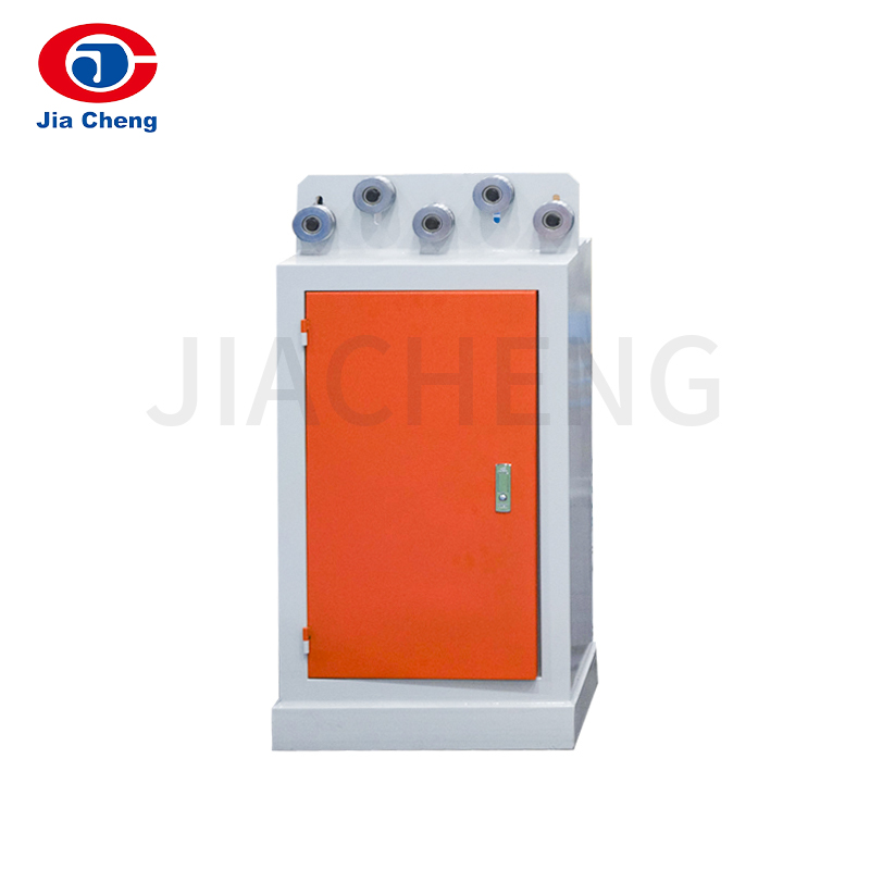
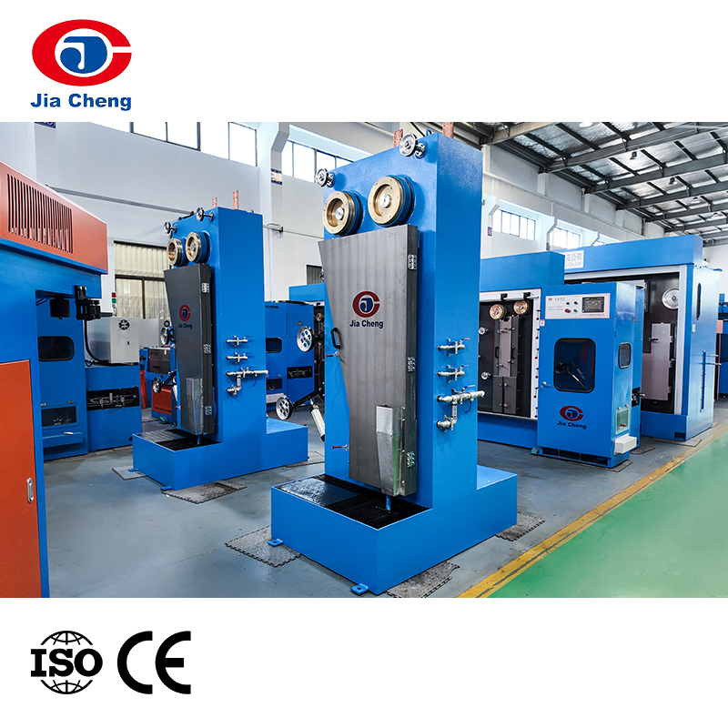 Online Continuous Annealing Machine for Cable Wire ProductionProvides continuous wire annealing for cable manufacturing, with horizontal or vertical structures and multiple models for different wire diameter ranges.View Product →
For higher output, multiwire machines draw four, eight, sixteen or even twenty-four wires in parallel through the same die sequence, which is how most volume producers keep fine wire costs down. The process control challenge grows with the number of lines, but so does throughput, and the per-kilometre energy consumption falls noticeably.
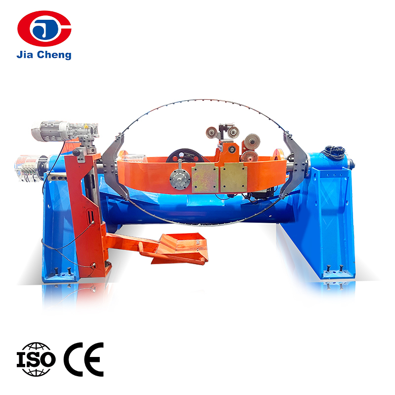
 Multiwire Drawing Machine for High-Output Fine Wire ProductionDraws multiple wires simultaneously with PLC control and online detection, supporting high-efficiency, large-scale production for volume fine wire manufacturing.View Product →
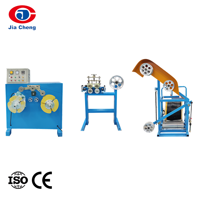
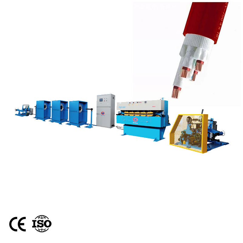
After drawing, the conductor is either used as a solid core or bunched into a stranded build, and then insulated. Our colleagues who look after fine wire processing equipment usually make the point that the drawing stage decides the resistance, while the extrusion stage decides the finished diameter. Both have to be right before a cable passes inspection.
Practical Checks Before You Convert a Gauge Value
Conversion tables are useful, but a few habits prevent most of the mistakes we see:
- Confirm which gauge system is being used, because AWG, SWG and non-electrical gauges are not the same scale.
- Confirm whether the number refers to the conductor, the core, or the finished cable outside diameter.
- Confirm the stranding, since the conductor area is fixed by the AWG value but the outside diameter is not.
- Verify with resistance or weight rather than diameter alone, especially on long runs where a small dimensional error compounds.
- Allow for normal tolerance and die wear, and use an online diameter gauge if tight dimensional control matters.
Frequently Asked Questions
Is 20 gauge wire the same as 0.5 mm²?
Very close, but not identical. A solid 20 AWG conductor measures 0.518 mm², about 3.6 percent more copper than a nominal 0.5 mm² conductor. In low-voltage control and signal applications the two are used interchangeably, but for resistance-critical or standards-governed designs it is better to keep the exact size on the drawing.
What is 20 AWG in mm for a stranded conductor?
The nominal area stays at 0.518 mm², but the outside diameter grows. A common 10 × 0.255 mm build measures roughly 0.95 to 1.0 mm across the bundle, depending on the lay length and compaction. Measuring a stranded conductor with a calliper will therefore never give you exactly 0.812 mm.
How many amps can 20 gauge wire carry?
For a single insulated copper conductor in free air, figures between about 5 and 11 A are commonly quoted, with the exact value depending on insulation class and permissible temperature rise. Inside a multi-core cable or bundle, the practical figure drops to roughly 1.5 to 3 A because heat dissipation is restricted.
Is 20 AWG thicker than 22 AWG?
Yes. Because the AWG scale runs in reverse, 20 AWG at 0.812 mm is thicker than 22 AWG at 0.644 mm. In terms of copper area, 20 AWG carries about 59 percent more metal than 22 AWG, which is why it has noticeably lower resistance.
Why does my 20 AWG wire measure 0.79 mm instead of 0.812 mm?
Small deviations are normal. Manufacturing tolerances for AWG conductors, die wear, slight ovality from the capstan, and the thickness added by tinning all affect the measured figure. Tinned wire typically measures slightly larger than bare copper, while worn dies tend to produce a slightly smaller diameter. If the resistance and elongation are within specification, a difference of one or two hundredths of a millimetre is usually not a concern.