Language
 中文简体
中文简体 English
 عربى
عربى русский
Content
- 1 What Is a Wire Drawing Machine
- 2 The Core Formula for Calculating Wire Drawing Machine Speed
- 3 Step by Step Worked Example
- 4 Factors That Affect Real World Wire Drawing Speed
- 5 Reference Speed Chart by Wire Diameter
- 6 How Capstan Diameter and Motor RPM Interact
- 7 Common Mistakes When Calculating Wire Drawing Machine Speed
- 8 Speed Guidance by Metal Type
- 9 Optimizing Wire Drawing Machine Speed for Productivity
- 10 Related Machinery Questions People Also Ask
- 11 Choosing a Wire Drawing and Winding Machine Supplier
- 12 Key Takeaways
A practical, formula based walkthrough for engineers, workshop managers and buyers who need to size capstan speed, predict output and understand what actually drives production rate on a wire drawing line.
The core method for how to calculate wire drawing machine speed is the capstan surface speed formula. For any capstan or take up spool, linear wire speed equals the circumference of the capstan multiplied by its rotation speed in revolutions per minute.
Where V is the wire speed in meters per minute, D is the capstan diameter in meters, and N is the capstan rotation speed in revolutions per minute. Because the wire gets thinner and longer as it passes through each die, the speed at every drawing station is different, and the true finishing speed must be calculated using the conservation of volume rule covered in section three below.
Wire drawing machine speed is one of the most misunderstood numbers on a production floor. Operators often quote a single figure, such as 800 meters per minute, without specifying which stage of the machine that number belongs to. In reality a multi die wire drawing machine runs at a different linear speed at every capstan, because the wire cross section shrinks at each pass while the volume of metal moving through the line per unit time stays constant. This guide breaks the calculation down step by step, gives worked examples with real numbers, explains the mechanical factors that limit achievable speed, and also answers several closely related questions about coil winding machines, wire mesh welding equipment and textile winding machinery that often come up in the same buying or engineering conversation.
What This Guide Covers
- What Is a Wire Drawing Machine
- The Core Speed Formula
- Step by Step Worked Example
- Factors That Change Real World Speed
- Reference Speed Chart by Wire Diameter
- Capstan Diameter and Motor RPM
- Common Calculation Mistakes
- Speed Guidance by Metal Type
- Optimizing Speed for Output
- Related Machinery Questions
- Choosing a Machine Supplier
What Is a Wire Drawing Machine
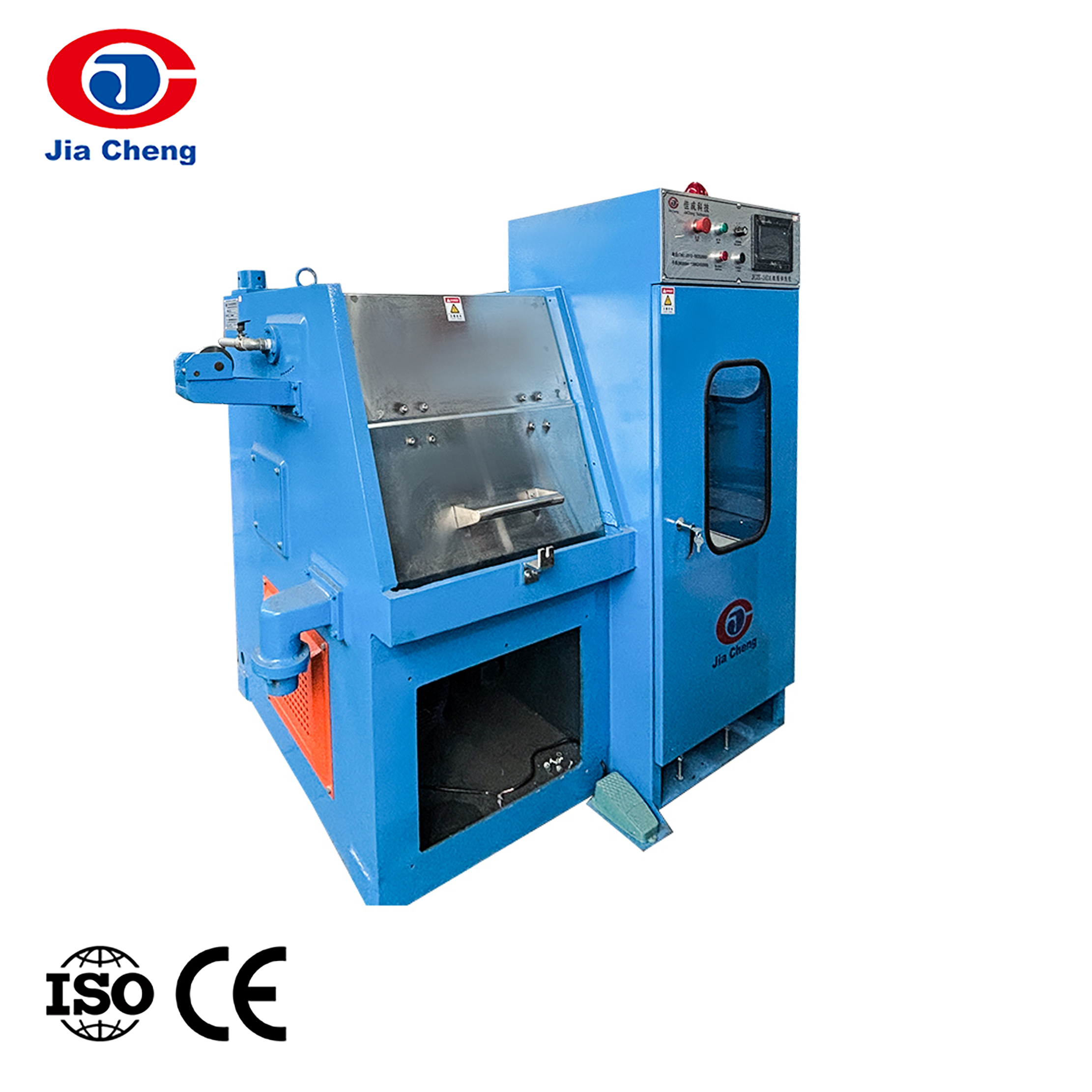
Before the speed calculation makes sense, it helps to answer a more basic question that many newcomers to the industry search for directly: what is a wire drawing machine. A wire drawing machine is a piece of metal forming equipment that reduces the diameter of a metal rod or wire by pulling it through a series of dies with progressively smaller openings. The metal is not cut or removed, it is stretched and compressed, so the cross sectional area gets smaller while the length gets proportionally longer. This is why wire drawing is described as a cold forming process rather than a machining process.
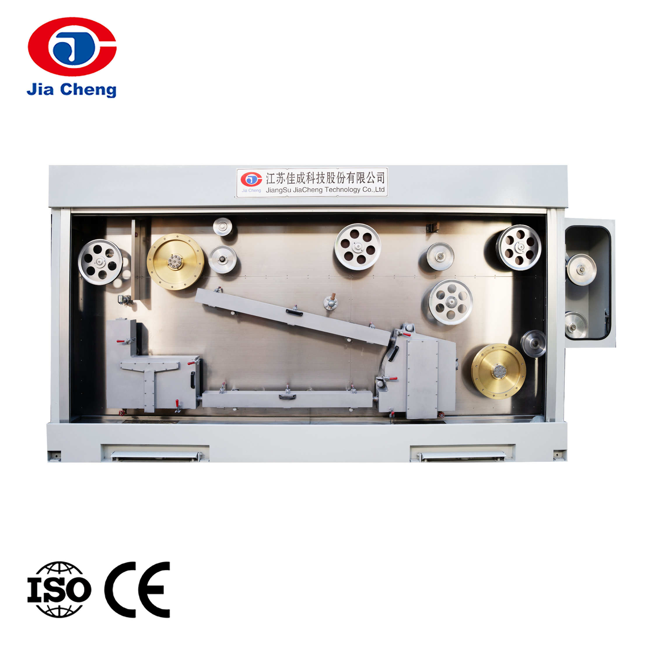
A typical wire drawing machine is built around a few core components: a pay off stand that holds the incoming rod or coarse wire, a series of drawing dies mounted in die boxes, a set of capstans (also called blocks or bull blocks) that pull the wire through each die and store the loop of wire needed for tension control, a lubrication and cooling system, and a take up unit that spools the finished wire. Machines are generally classified as single block, multi block or straight line, and can be built for dry drawing or wet drawing depending on whether lubricant is applied as powder or as a liquid bath.
The reason speed calculation matters so much on this type of equipment is that every capstan in the chain must run at a slightly different rotational speed. If the speed at any capstan is wrong relative to its neighbors, the wire will either go slack, which causes wraps and tangling, or it will be over tensioned, which causes the wire to stretch, thin unevenly or snap. Getting the speed relationship right across the whole machine is the single most important setup task for any wire drawing operator.
The Core Formula for Calculating Wire Drawing Machine Speed
There are really two layers to this calculation. The first layer is the mechanical speed of a single capstan, which is simple geometry. The second layer is the speed relationship between capstans, which is based on conservation of volume, sometimes called the constant volume rule.
1Single Capstan Surface Speed
Every capstan pulls wire at a linear speed equal to its surface speed, because the wire is wrapped tightly around it with no slippage under normal operation. The formula is:
V is the linear wire speed leaving that capstan, D is the effective diameter of the capstan measured to the center of the wire wraps, and N is the rotational speed of the capstan in revolutions per minute. Pi is approximately 3.1416.
2Constant Volume Between Drawing Passes
As wire passes through a die, its cross sectional area decreases but the volume of metal moving through the line per second cannot change, since metal is neither created nor destroyed in the process. This gives the constant volume relationship between any two consecutive passes:
A1 and V1 are the cross sectional area and speed before a given die, A2 and V2 are the area and speed after that die. Since cross sectional area of round wire is proportional to the square of the diameter, this can be rewritten in terms of diameter:
This is the formula that explains why the last capstan on a multi block wire drawing machine always spins dramatically faster than the first one. A wire that starts at 3.0 millimeters and finishes at 1.0 millimeter has its cross section reduced by a factor of nine, so the exit speed is nine times higher than the entry speed, even though the same length of finished wire is produced per minute as feet of raw rod consumed, once you account for the total elongation.
3Output Rate From Speed
Once the finishing speed is known, converting it into a production rate is straightforward using the linear mass of the wire:
Linear weight depends on the wire diameter and the density of the metal being drawn. For copper wire, linear weight in kilograms per meter is roughly the cross sectional area in square millimeters multiplied by 0.0089. For steel wire the multiplier is close to 0.00785.
Step by Step Worked Example
The clearest way to understand how to calculate wire drawing machine speed is to work through a realistic example from raw rod to finished coil.
Define the entry and exit conditions
Assume a copper wire drawing machine takes in rod at 2.6 millimeters diameter and the final capstan pulls finished wire at 0.8 millimeters diameter. The first capstan diameter is 0.32 meters and it turns at 45 revolutions per minute.
Calculate entry speed at the first capstan
V1 = pi x 0.32 x 45 = about 45.2 meters per minute. This is the speed at which rod is being drawn through the first die.
Apply the constant volume rule to the final diameter
V2 = V1 x (2.6 / 0.8) squared = 45.2 x 10.56 = about 477 meters per minute. This is the theoretical exit speed at the last die if the whole reduction happened in a single pass.
Check the last capstan geometry against that target
If the final capstan diameter is 0.22 meters, the required rotation speed is N = V2 / (pi x D) = 477 / (pi x 0.22) = about 690 revolutions per minute. This tells the operator what motor and gearbox setting the last block needs to match the line.
Convert to an output rate
At 0.8 millimeters diameter, cross sectional area is about 0.503 square millimeters, giving a linear weight of roughly 0.00448 kilograms per meter for copper. Output = 477 x 60 x 0.00448 = about 128 kilograms per hour from this single wire drawing machine.
Practical note. Real machines rarely hit the theoretical single pass speed exactly, because slip factors between one and three percent are normal on intermediate capstans to maintain correct back tension, and every die also introduces a small amount of tension loss that a skilled setter compensates for with slightly higher speed on later blocks.
Factors That Affect Real World Wire Drawing Speed
The formulas above describe the ideal case. In an actual workshop, several mechanical and material factors push the achievable speed up or down from that theoretical number.
Die Reduction Schedule
A shallow reduction per die allows higher speed with less risk of breakage. An aggressive reduction schedule forces slower speed to control heat and stress in the wire.
Lubrication Quality
Poor lubrication increases friction and die wear, which limits maximum safe speed. Wet drawing machines can generally run faster than dry drawing machines on the same material.
Material Ductility
Soft, highly ductile metals such as annealed copper and aluminum tolerate higher drawing speed than harder alloys such as stainless steel or high carbon steel wire.
Motor and Gearbox Rating
The installed motor power and gearbox ratio set a hard ceiling on capstan rotation speed regardless of what the theoretical formula suggests is possible.
Cooling Capacity
Drawing generates heat through friction and deformation. If cooling cannot keep up with speed, the wire and dies overheat, which shortens die life and can change grain structure.
Die Condition and Alignment
Worn or misaligned dies increase drag and vibration, forcing operators to reduce speed to avoid surface defects or wire breaks.
| Factor | Effect on Achievable Speed | Typical Adjustment |
|---|---|---|
| Reduction per die | Higher reduction lowers safe speed | Keep reduction near 15 to 22 percent per pass for most metals |
| Lubricant type | Liquid lubricant supports higher speed than dry soap | Switch to wet drawing above roughly 400 meters per minute |
| Wire hardness | Harder alloys need lower speed and more passes | Add intermediate annealing for hard steel or stainless wire |
| Die wear | Worn dies raise friction and defect risk | Inspect and rotate dies on a fixed hour based schedule |
| Capstan cooling | Poor cooling forces speed reduction to avoid overheating | Add water cooled capstan jackets on high speed lines |
Reference Speed Chart by Wire Diameter
The chart below gives typical finishing speeds for medium duty copper wire drawing machines at different final wire diameters. These are representative workshop figures, not a substitute for the manufacturer rated speed of a specific machine.
Notice that finishing speed generally rises as the target diameter gets finer. This follows directly from the constant volume formula in section two, since a smaller final cross section requires proportionally higher linear speed to move the same volume of metal per minute.
How Capstan Diameter and Motor RPM Interact
Because V equals pi times D times N, there are always two ways to reach a target line speed: a larger capstan turning slower, or a smaller capstan turning faster. Machine builders choose capstan diameter based on wire tension limits and floor space, then size the drive motor and gearbox to deliver the RPM range that matches the desired speed window.
This chart shows four different capstan diameters set up to reach roughly the same 700 to 900 meters per minute surface speed range purely by changing RPM. Larger capstans need proportionally less RPM to hit the same linear speed, which reduces bearing wear and vibration but takes up more machine length.
Design tip. When a machine builder increases capstan diameter to lower operating RPM for a given speed target, remember to recompute every downstream capstan diameter and RPM using the same constant volume relationship, otherwise the tension balance between blocks will be wrong even though the final line speed looks correct on paper.
Common Mistakes When Calculating Wire Drawing Machine Speed
Using outer capstan diameter
Always measure to the pitch line of the wire wraps, not the bare drum diameter, or the speed figure will be consistently too low.
Ignoring die wear over time
A worn die passes wire at a slightly larger diameter than its nominal size, which quietly changes the reduction ratio and the true exit speed.
Forgetting slip allowance
Treating every capstan as zero slip leads to tension errors, since real machines are usually set with a small planned speed differential between blocks.
Mixing units
Diameter in millimeters must be converted to meters before it is used in the meters per minute formula, a step that is easy to miss under time pressure.
Speed Guidance by Metal Type
Different metals have different maximum practical drawing speeds because of how they work harden and how much heat the process generates in them.
| Metal | Typical Speed Range | Notes |
|---|---|---|
| Copper | 300 to 900 meters per minute | Excellent ductility, supports the highest routine speeds |
| Aluminum | 250 to 800 meters per minute | Similar to copper but more sensitive to die polish and heat |
| Low carbon steel | 150 to 500 meters per minute | Needs more frequent intermediate annealing at fine gauges |
| High carbon steel | 80 to 300 meters per minute | Slower passes and closer temperature control required |
| Stainless steel | 60 to 250 meters per minute | Higher work hardening rate limits speed and reduction per die |
Optimizing Wire Drawing Machine Speed for Productivity
Once the calculation method is understood, the practical goal shifts from what speed is theoretically possible to what speed is sustainable across a full production shift. A few adjustments consistently deliver the biggest gains without new capital equipment.
Balance the reduction schedule
Spread the total reduction evenly across all dies rather than taking a heavy cut early and light cuts later, which lets every capstan run closer to its practical maximum.
Match lubricant to speed target
Upgrading from dry soap lubrication to a circulated liquid lubricant with proper filtration is often the single change that unlocks the next speed tier.
Keep die inventory fresh
A structured die replacement schedule based on drawn length rather than calendar time keeps the whole line running at its rated speed instead of quietly slowing down as dies wear.
Verify motor headroom before pushing speed
Recalculate required torque and power at the new target speed before increasing RPM, since exceeding motor rating leads to nuisance trips and shortened drive life.
Choosing a Wire Drawing and Winding Machine Supplier
Getting the speed calculation right on paper is only useful if the machine itself is built with accurate capstan diameters, a properly rated drive train and consistent die tooling. This is why the supplier behind the equipment matters as much as the formula used to size it.
Jiangsu Jiacheng Technology Co., Ltd.
Jiangsu Jiacheng Technology Co., Ltd. supplies wire drawing machines, coil winding machines and related wire processing equipment built around consistent capstan geometry and reliable drive systems, which makes the speed calculations in this guide translate directly into predictable output on the shop floor. Their engineering team supports customers through the full sizing process, from selecting capstan diameter and motor rating to matching die reduction schedules to the specific alloy being drawn.
Key Takeaways
Calculating wire drawing machine speed comes down to two formulas used together: the simple surface speed formula V equals pi times D times N for any single capstan, and the constant volume rule that links speed and diameter across every drawing pass on the line. Once those two relationships are understood, sizing a new machine, diagnosing a tension problem, or estimating output for a production quote all become straightforward arithmetic rather than guesswork. Pair the calculation with attention to lubrication, die condition and motor headroom, and the theoretical numbers in this guide will hold up closely to what actually happens on the factory floor.